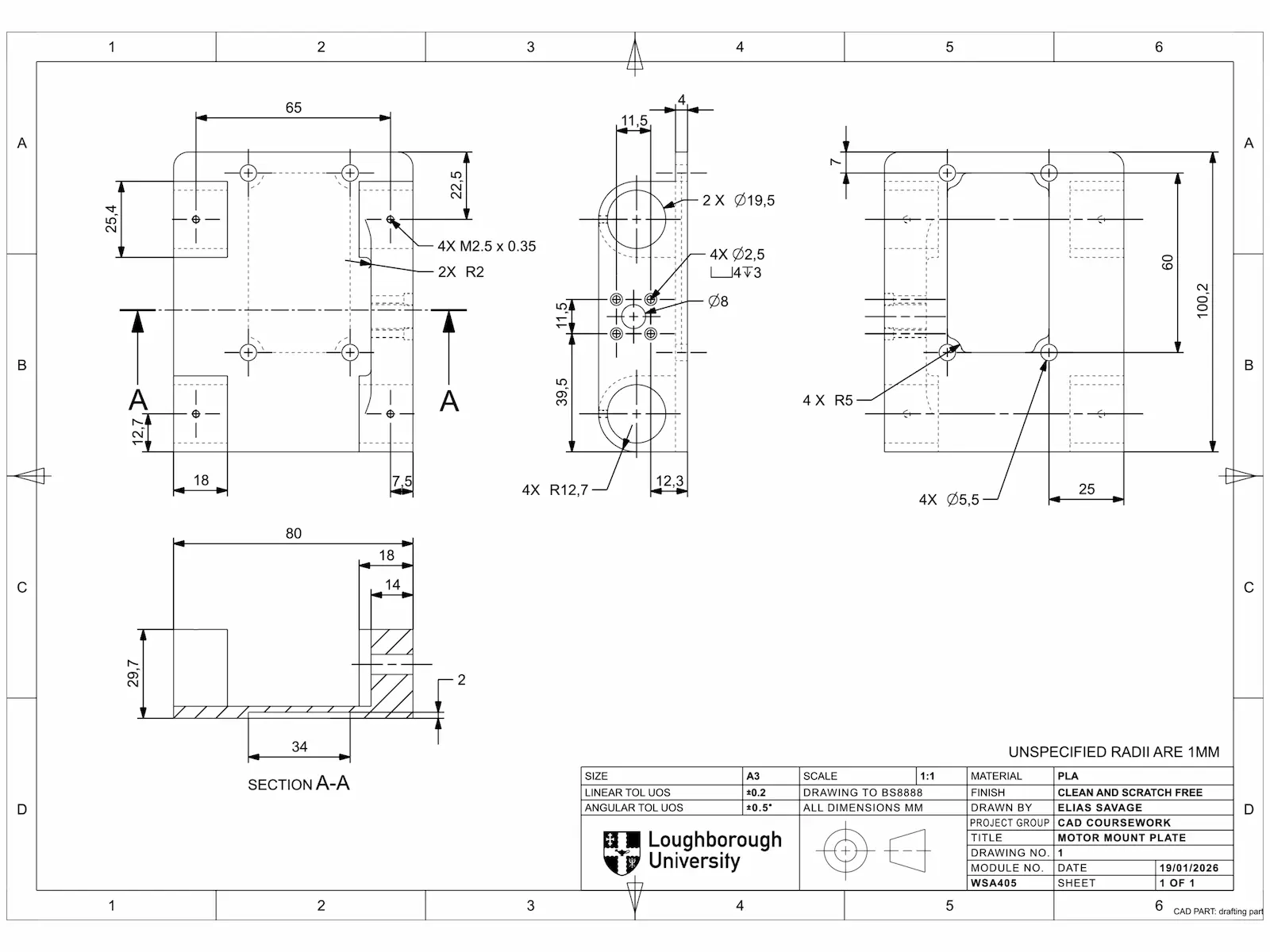
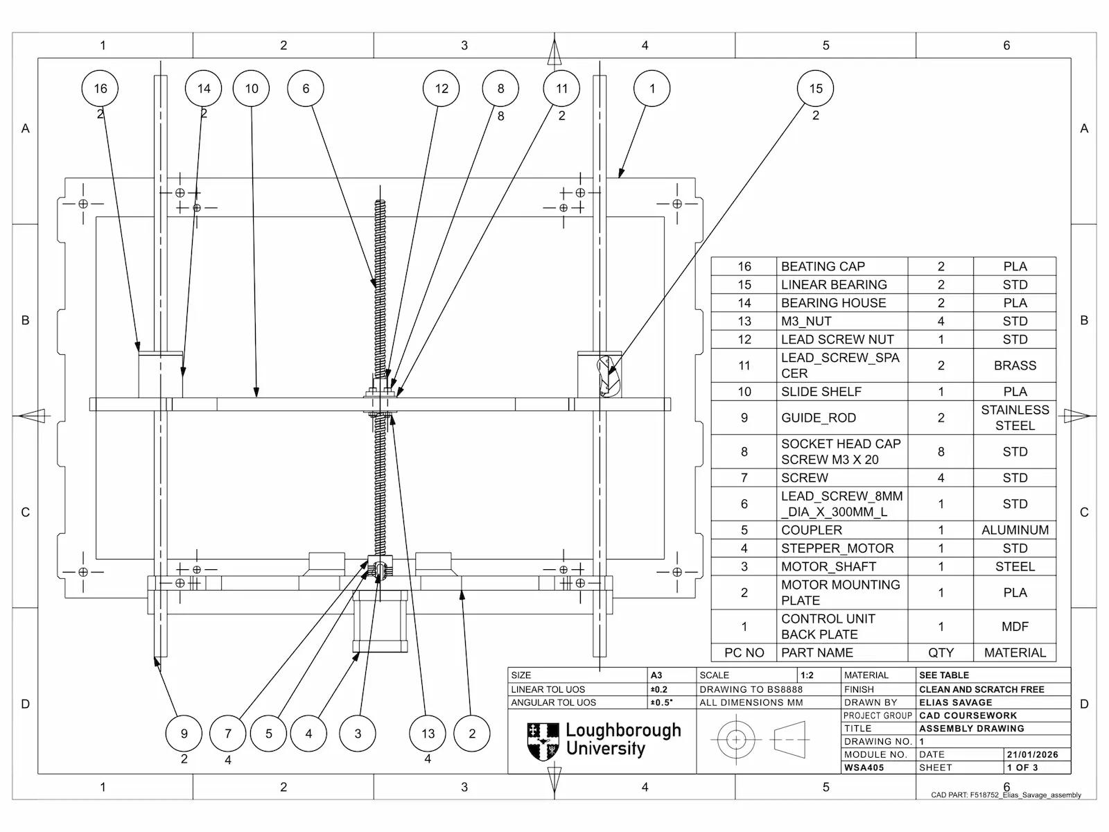
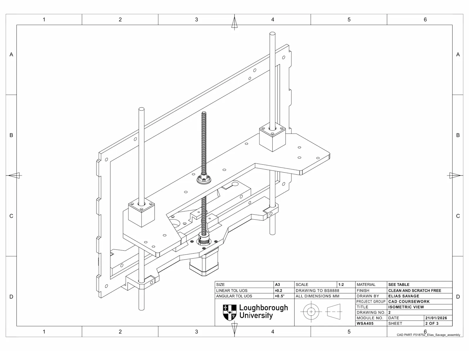
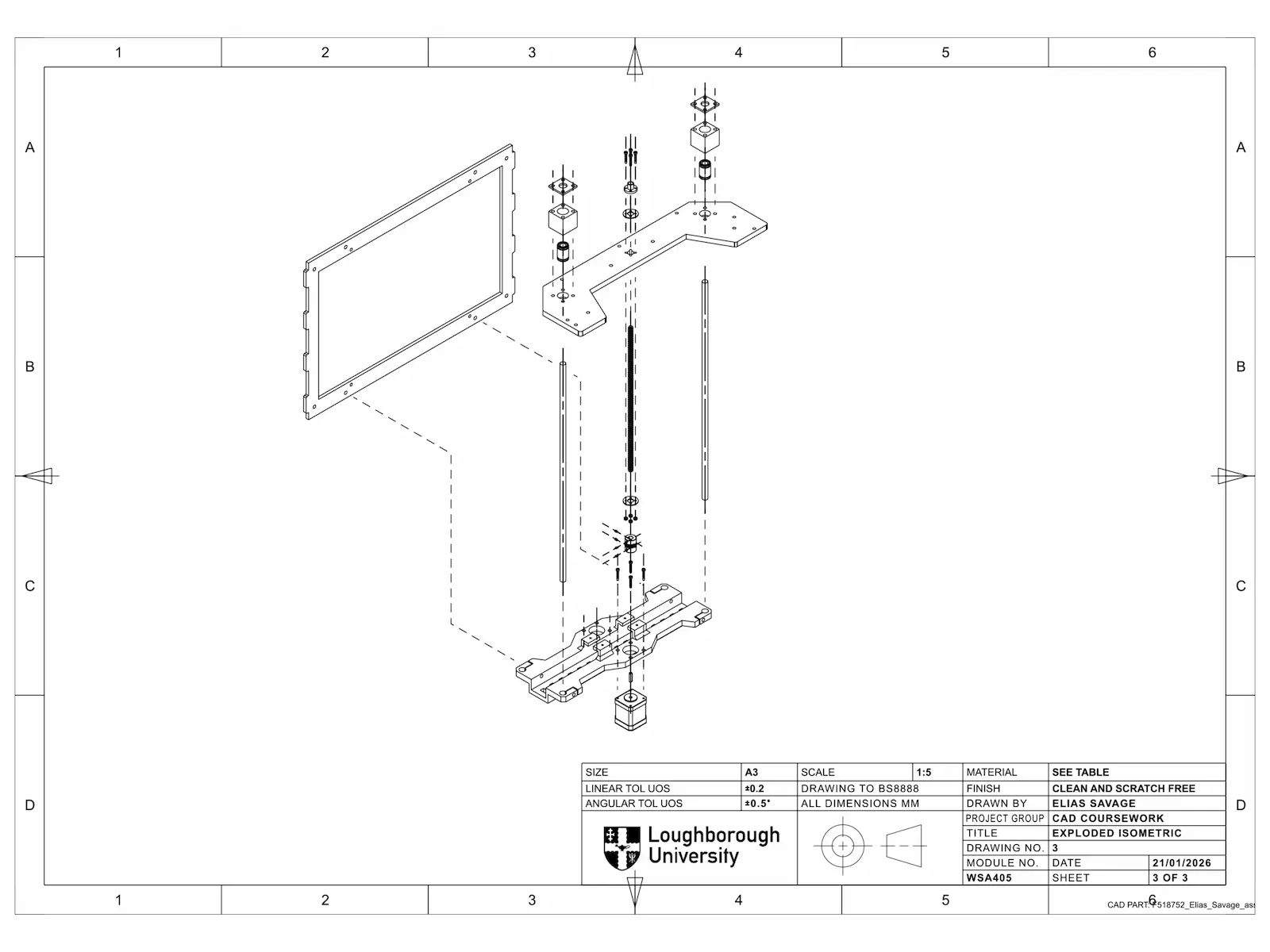
This is a BS 8888 (ISO-aligned) engineering drawing coursework. The coursework consisted of two parts: a fully dimensioned part drawn to standard and a fully labelled and constrained assembly.
For Sheet 1 of 1 (top left) I was given a complete CAD part, which was a motor mounting plate, and had to produce a fully dimensioned drawing from it. This consisted of choosing the correct orthographic views, picking a section that clearly showed the internal features, and applying the correct dimensions without repeating any dimensions.
For the assembly, I was given all the parts and a video of how they need to fit together. First I built the assembly using the correct mates and constraints to ensure that all the parts could move in the correct planes of motion. I then documented the assembly across three sheets. Sheet 1 of 3 shows a fully labelled view of the assembly, using breakout section views to show parts which aren't visible, such as the motor shaft and linear bearing. Sheet 2 of 3 (bottom left) shows an isometric view of the assembly, and Sheet 3 of 3 (bottom right) shows an exploded isometric view of the assembly with the correct trace lines.